Method
revAMp Fabrication Method
The fabrication method for revamping building sites or architectural elements will include an experimental workflow of object scanning, sensory positioning, mobile robot navigation and in situ 3D printing. In this context, a fabrication method will be set up and explored in which damaged parts of an architectural building component are revAMped through an informed in-situ 3D printing process.
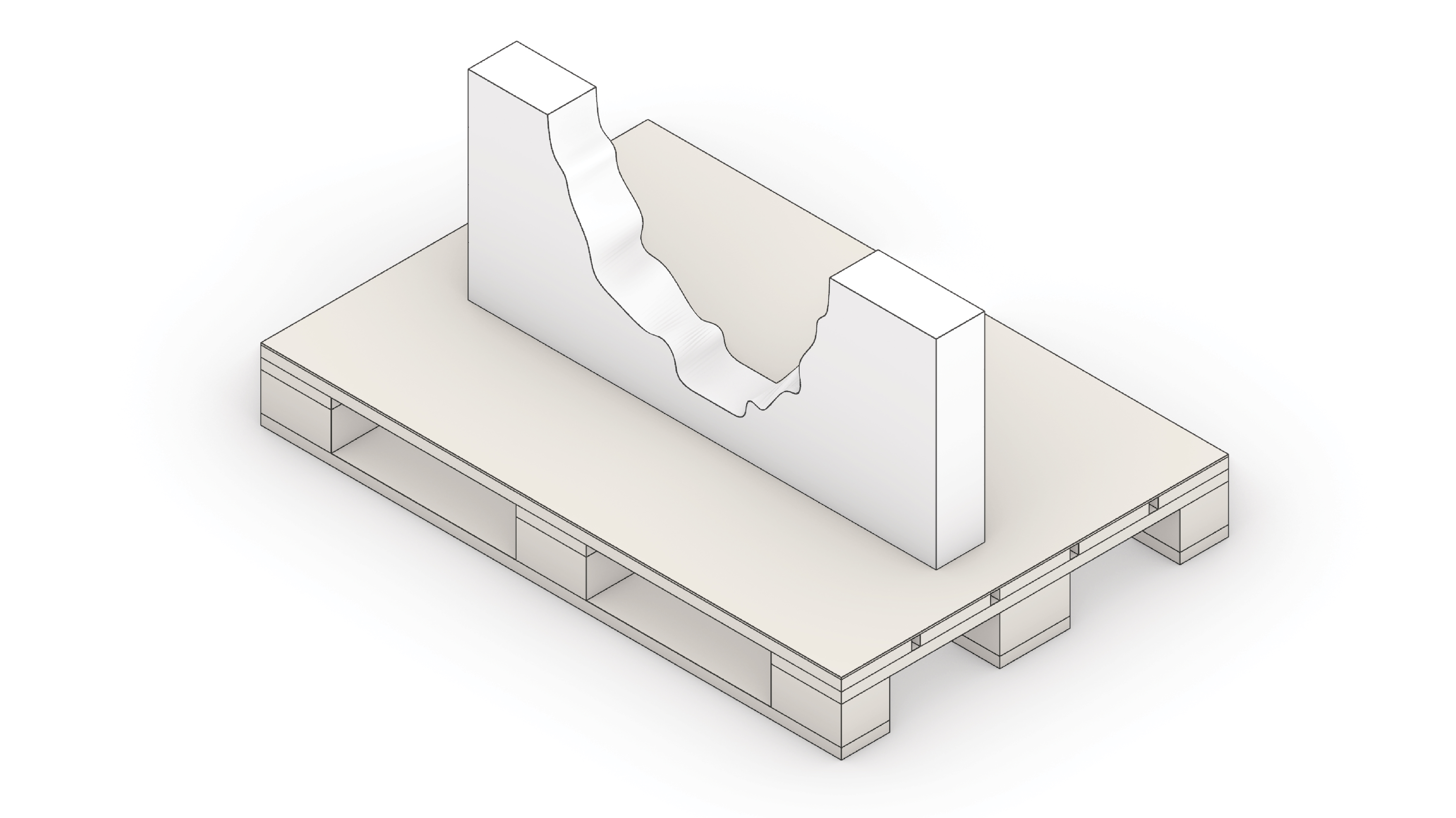
Step 1: 3D Object to be revAMped
In this step, the broken building element is selected and stationed.
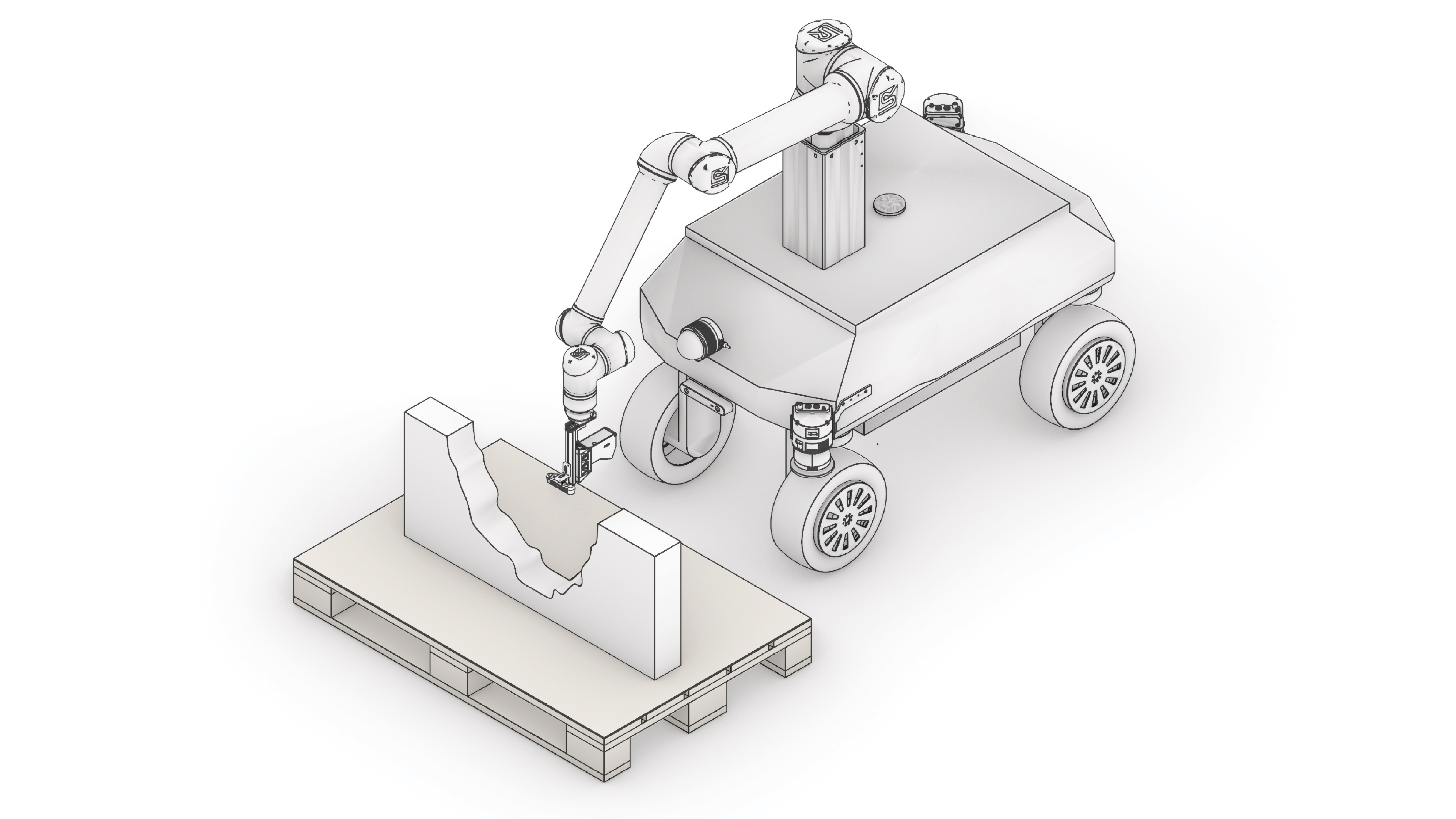
Step 2: Driving the mobile-robot to the building element
Here, a manual intervention is utilized to drive the mobile-robot near the selected object. The mobile robot will be equipped with an onboard camera-based sensing system to roughly recognize the geometric shape.
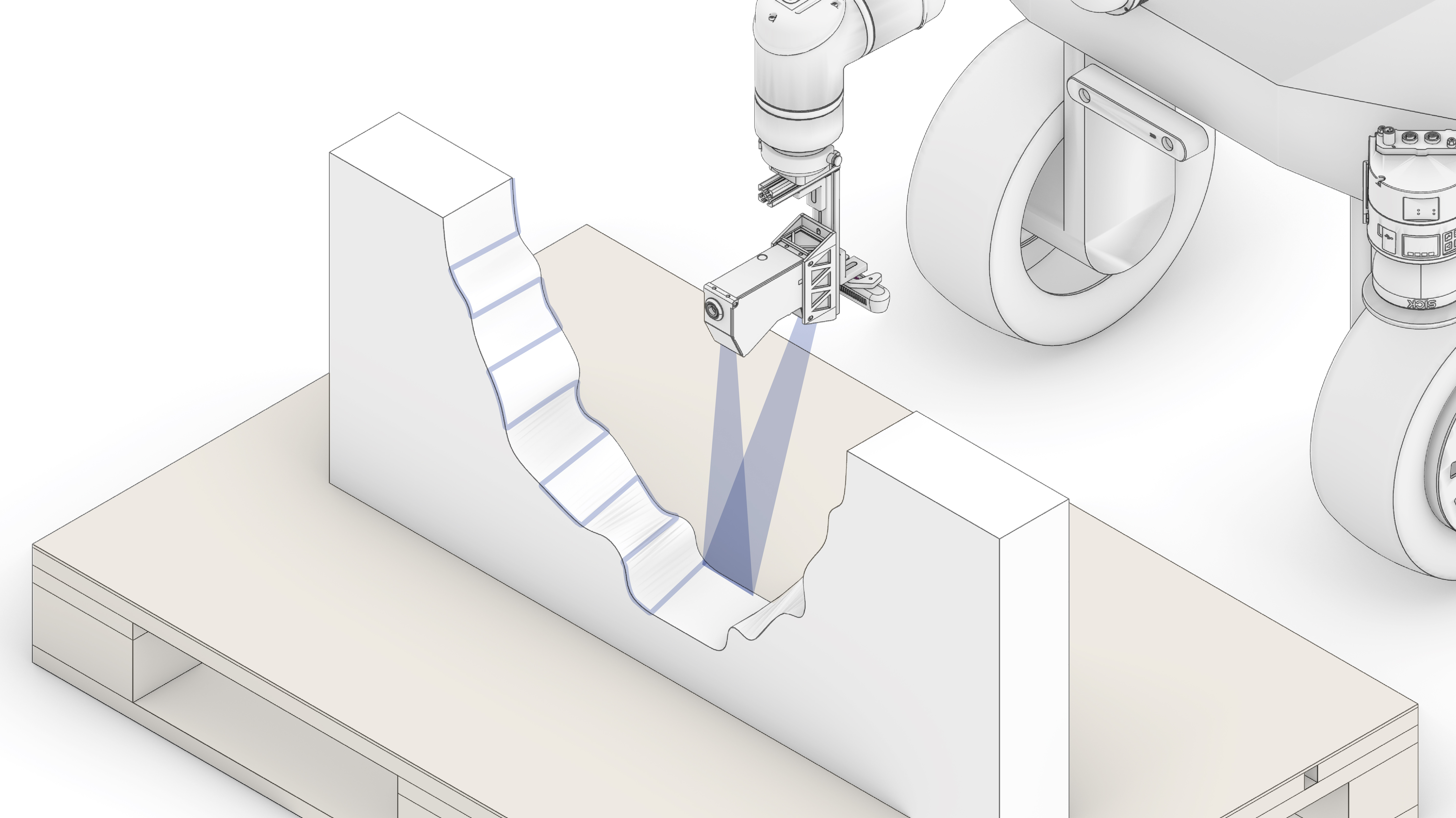
Step 3: Real Sense Positioning
This step includes (manually) positioning and rotating the camera sensor in relation to the object to capture a proper field view for data collection.

Step 4: Scanning Trajectory
Here, identifying the exact area for refined laser-scanning from the camera image is conducted and overlayed with a zig-zag scanning path.
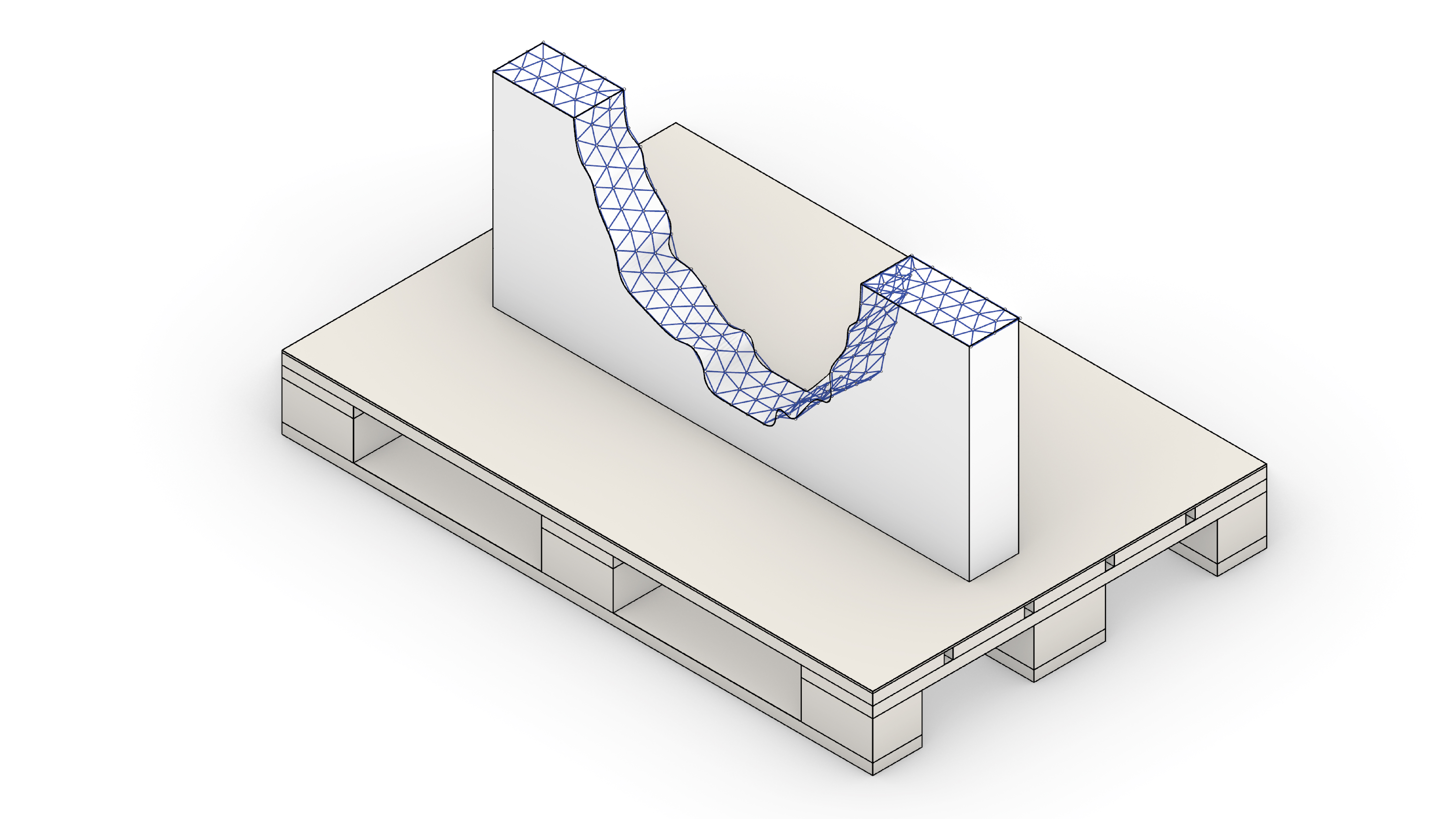
Step 5: Point Cloud Collection and Evaluation
In this step, the point-clouds are collected by moving the scanner along the predefined scanning path. Single scans are registered through transforming each line scan along the robot joints.
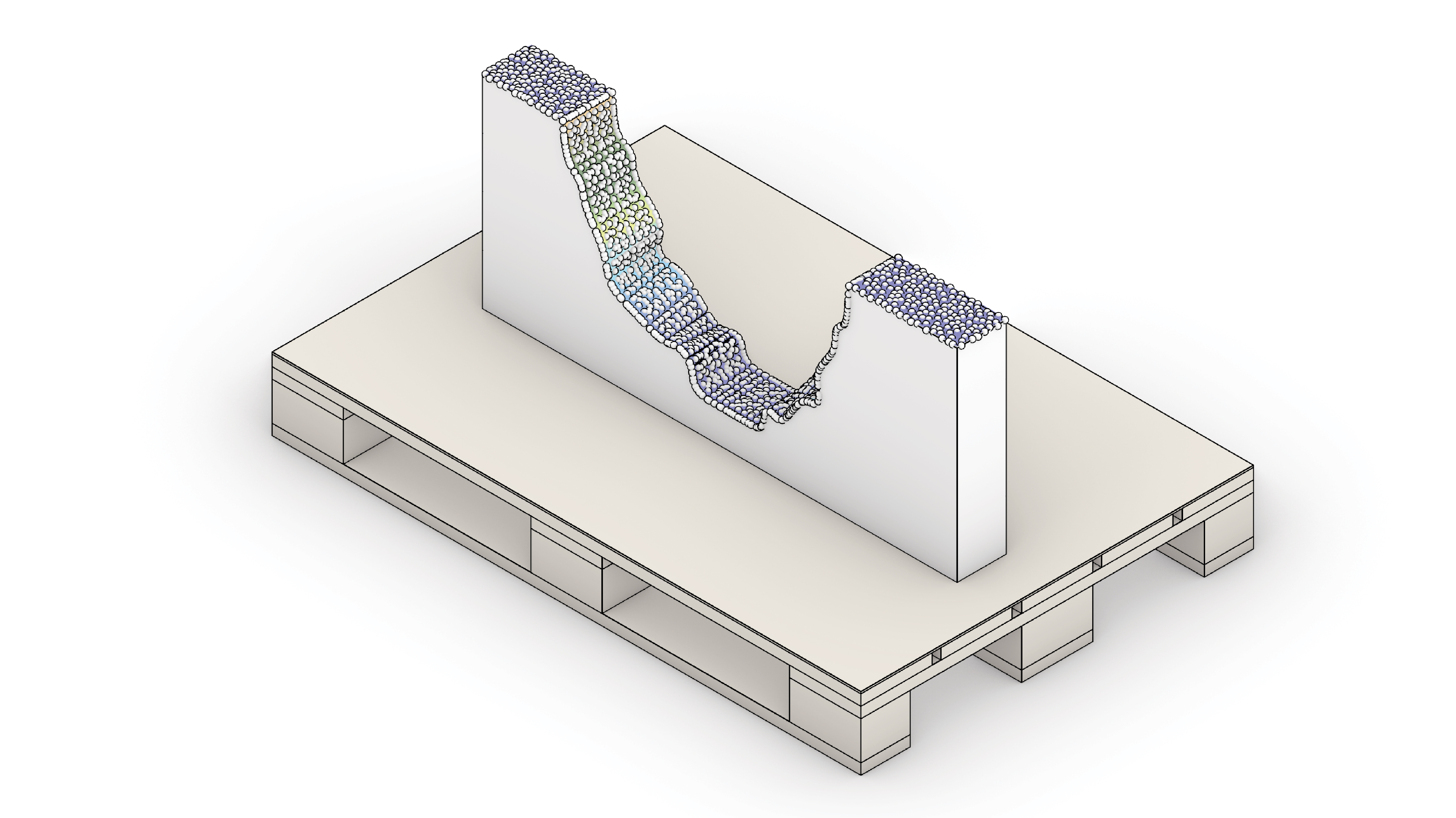
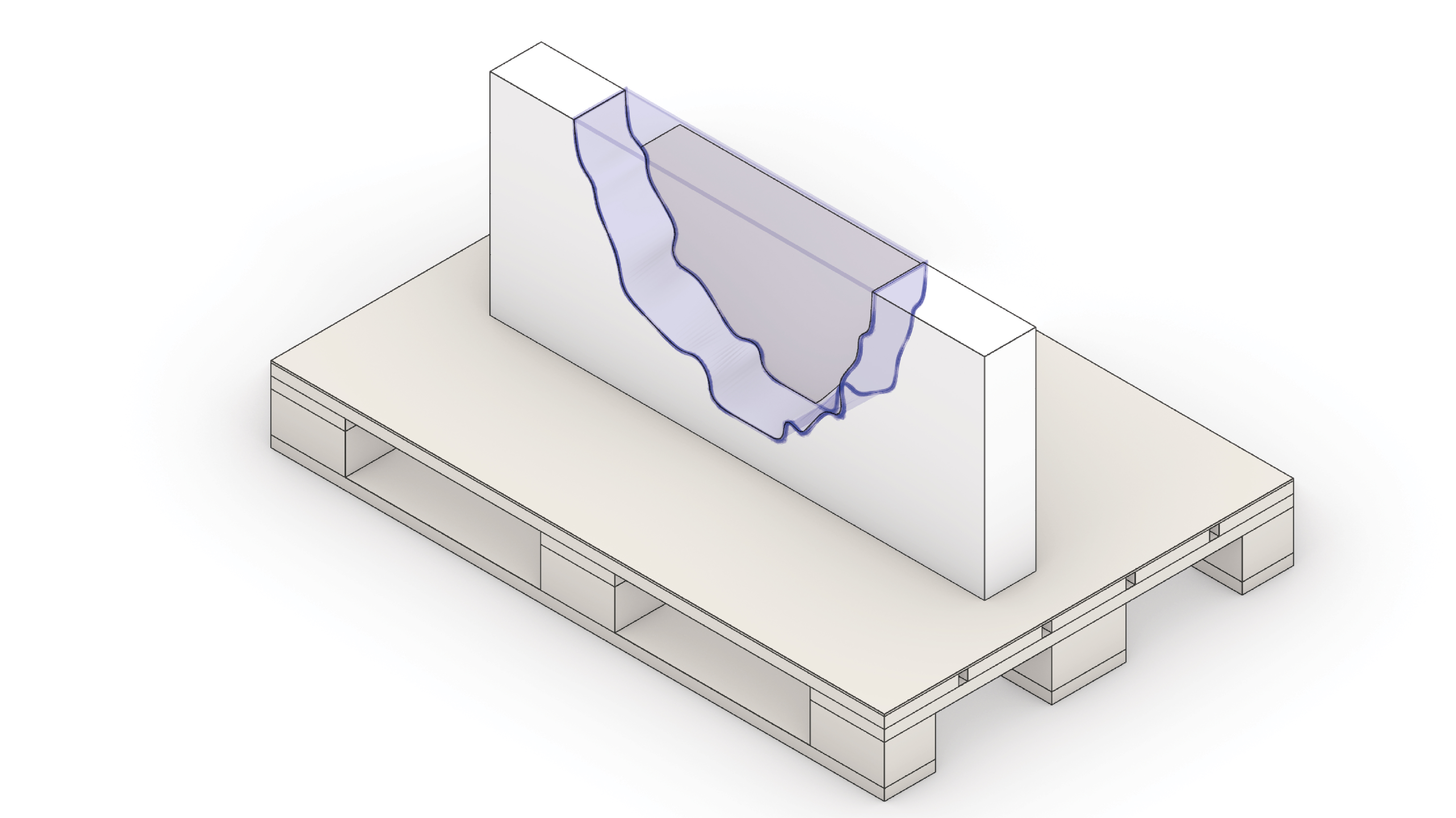
Step 6: Surface Re-construction
For further path-planning a closed surface is reconstructed based on the registered point-cloud. Compensation of scanning errors is performed by ~80% subsampling of the initial data sets.
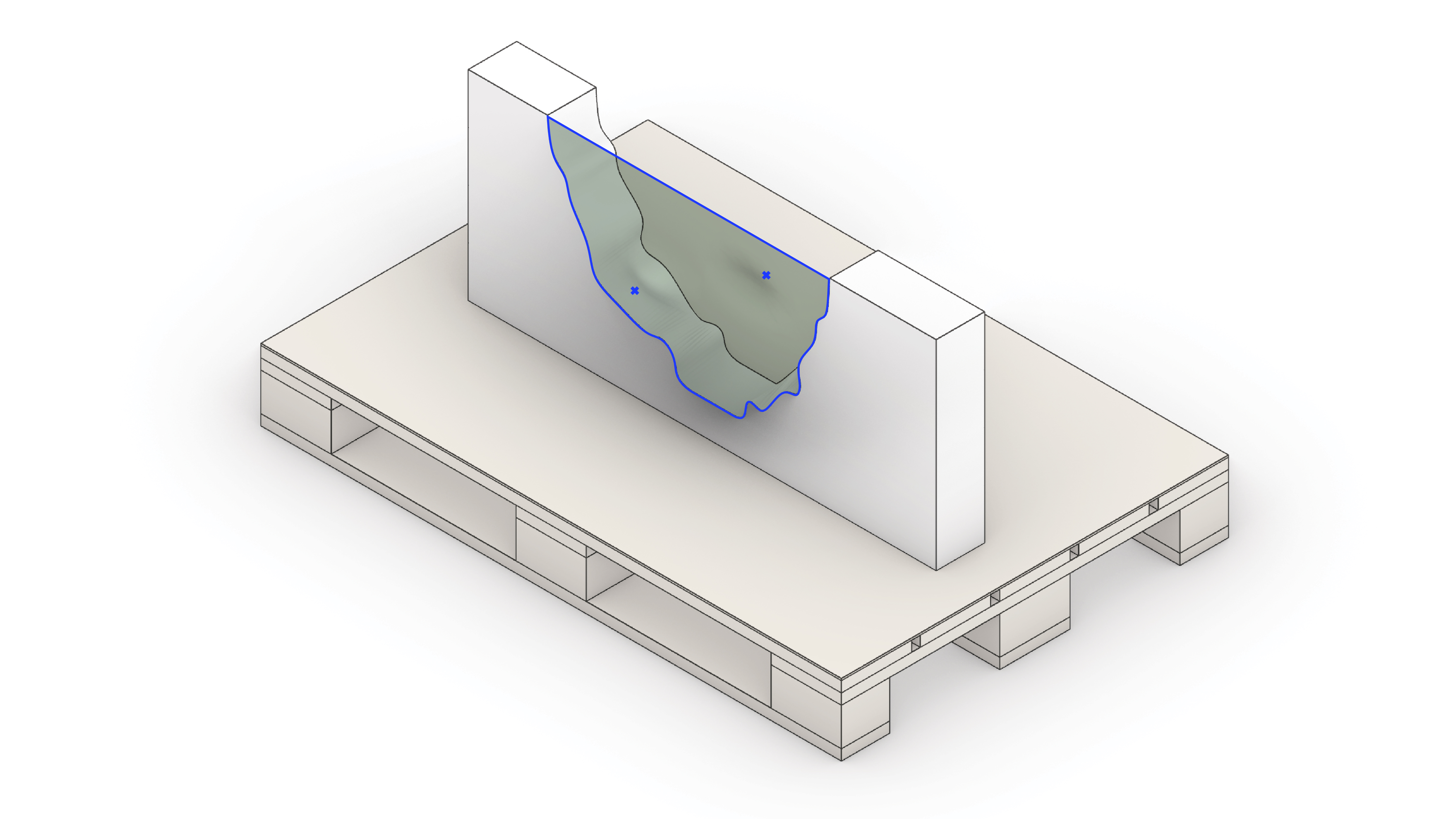
Step 7: Printing Region Identifying
The reconstructed surface is utilized to trim the to-be-printed geometry.
Step 8: Printing Path Design Generation
Here, the identified printing regieon is designed.
Step 9: Path Print Simulation
The printing path is simulated visually and it’s executed from the generated revAMp design.

Step 10: Extrusion 3D Printing
In this step, the mobile-robot will be equipped with an extrusion end-effector for the 3D Printing Process. The extrusion 3D Printing Process with clay has been developed in previous research projects and its controlled parameter such as (speed, distance from the surface, start and stop function,…) will be implemented.
